

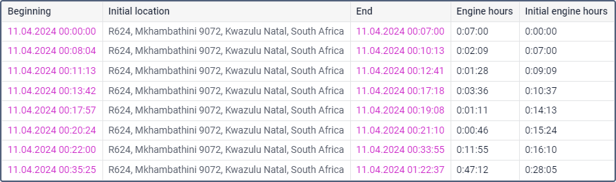
The Engine hours report shows how long the unit worked, how much time was in motion, how much fuel was spent for this period. Also, the duration and efficiency of the work of the attachable equipment can be shown.
To generate this report, the unit is supposed to have such sensors as ignition or absolute/relative engine hours sensor. The method of calculating engine hours is set in unit properties on the General tab. On the Advanced tab, you can also set Daily engine hours rate to calculate utilization and productivity.
In the report template, you can specify the mask for the main engine hours sensor that is used in the report (the Engine hours sensor filter). This allows you to separate the engines and create a table for each of them.
There are two options that can be used in the engine hours report. They are timeout (set for a sensor) and maximum interval between messages (set for a unit). Both options are used to cut off invalid intervals when the amount of engine hours is defined. If values for both timeout and maximum interval between messages are indicated, the system will use the property with the minimum value indicated.
The table can include the columns described below.
| Column | Description |
|---|---|
| Beginning | The time when the engine hours interval begins. |
| Initial location | The location of the unit when the engine or implement starts working. |
| End | The time when the engine hours interval ends. |
| Final location | The location of the unit when the engine or implement ends working. |
| Engine hours | The value of engine hours at the interval. For an accurate calculation of engine hours, the device should send a valid value of the selected sensor. In case of receiving an invalid value, it is necessary to replace the sensor with a validator using the correct value. |
| Initial engine hours | The value of the Absolute engine hours sensor at the start of the engine hours interval. If there are no values of this sensor within the interval for which the report is being executed, the initial value of the engine hours is calculated using the counter from the beginning of the interval to the first engine hour interval. In this case, the hour count starts from 0. If the sensor has sent a message with data not included in the scope of the engine hour interval, but included in the interval for which the entire report is being executed, the engine hour value is calculated by the counter with consideration of the absolute engine hour sensor data. |
| Final engine hours | The value of the sensor Absolute engine hours at the end of the interval. Calculated based on the initial engine hours. |
| Total time | The time from the start to the end of engine hours interval. It is recommended to use this column in combination with the grouping parameter or the Total row. If the Total row is configured in the table, it shows all the time that elapsed from the start of the first engine hours interval to the end of the last one. |
| Off-time | The period of time passed from the end of the previous interval to the beginning of the current one (determined starting from the second interval). |
| In motion | The interval of time during which the unit moved, that is, the speed value was greater or equal to the one from the Min moving speed field in the trip detector. |
| Idling | The time when the unit was standing with the engine on. Note that idling cannot be detected if the equipment does not send messages containing speed value. |
| Mileage | The distance travelled during the operating hours. |
| Mileage (adjusted) | Mileage subject to the coefficient set in the unit properties (the Advanced tab). |
| Initial mileage | The value of the mileage sensor at the moment of the beginning of the reporting period. |
| Final mileage | The value of the mileage sensor at the end of the reporting period. |
| Avg speed | The average speed during the interval of engine operation. |
| Max speed | The maximum speed during the interval of engine operation. |
| Counter | The counter sensor value. |
| Initial counter | The counter value at the beginning of the interval. |
| Finale counter | The counter value at the end of the interval. |
| Avg engine revs | The average rate of engine revolutions. |
| Max engine revs | The maximum rate of engine revolutions. |
| Avg temperature | The average temperature value registered for the interval of engine operation. |
| Min temperature | The minimum temperature value registered for the interval of engine operation. |
| Max temperature | The maximum temperature value registered for the interval of engine operation. |
| Initial temperature | The temperature value at the beginning of the engine hours operation. |
| Final temperature | The temperature value the end of engine hours operation. |
| Status | The unit status registered during the engine hour interval. It can be registered manually or automatically by means of a notification. If there are several registered statuses, the first of them is displayed. |
| Cargo weight | The average value of cargo weight during the engine hours interval. |
| Driver | The name of the driver (if assigned). |
| Trailer | The name of the trailer (if assigned). |
| Movement productivity | The percentage ratio of engine hours in the movement to the duration of engine hours. |
| Engine efficiency duration | The duration of the operation of attached equipment (if there is the engine efficiency sensor). |
| Engine efficiency idling | The engine operation time after deduction of efficiency time (total engine hours subtract engine efficiency duration). |
| Utilization | The percentage ratio of the duration of engine hours to engine hours rate (engine hours divided by daily engine hours rate indicated in the unit properties in the Advanced tab). |
| Useful utilization | The percentage ratio of the duration of engine efficiency to the engine hours rate. |
| Productivity | The percentage ratio of the duration of engine efficiency to the duration of engine hours. |
| Consumed | The volume of consumed fuel detected by any sort of fuel sensor. If several sensors are available, their values sum up. |
| Consumed by ImpFCS/AbsFCS/InsFCS/FLS/math/math for FLS/rates | The fuel volume detected by a fuel sensor or calculated by math or rates. |
| Avg consumption | The average fuel consumption by all available fuel sensors. |
| Avg consumption by ImpFCS/AbsFCS/InsFCS/FLS/math/math for FLS/rates | The average fuel consumption detected by a fuel sensor or calculated by math or rates. |
| Consumed by ImpFCS/AbsFCS/InsFCS/FLS/math/math for FLS/rates in motion | The fuel volume used in engine hours while moving. |
| Avg consumption in motion by ImpFCS/AbsFCS/InsFCS/FLS/math/math for for FLS rates | The average consumption in engine hours while moving. |
| Consumed in idle run by ImpFCS/AbsFCS/InsFCS/FLS/math/rates | The fuel volume used in engine hours during idle running. |
| Avg consumption in idle run by ImpFCS/AbsFCS/InsFCS/FLS/math/math for FLS/rates | The average fuel consumption in idling. |
| Avg consumption by ImpFCS/AbsFCS/InsFCS/FLS/math/math for FLS/rates in trips | The average fuel consumption in trips. |
| Initial fuel level | The fuel level at the beginning of the interval. |
| Final fuel level | The fuel level at the end of the interval. |
| Max fuel level | The maximum fuel level during the engine hours interval. |
| Min fuel level | The minimum fuel level during the engine hours interval. |
| Penalties | The penalties calculated for the adjusted Eco driving criteria. |
| Rank | The received penalty points converted into a grade using 10-point scoring system. |
| Avg value of custom sensor | The average value of a custom sensor during the engine hours interval. This and the following columns of custom sensor values show 0 if the value is invalid. For example, if the value is not within the bounds set in the calculation table. |
| Min value of custom sensor | The minimum value of a custom sensor during the engine hours interval. |
| Max value of custom sensor | The maximum value of a custom sensor during the engine hours interval. |
| Initial value of custom sensor | The value of a custom sensor at the beginning of the engine hours interval. |
| Final value of custom sensor | The value of a custom sensor at the end of the engine hours interval. |
| Notes | An empty column for your custom comments. |
For the engine hours report, you can apply interval filtration by engine hours sensor, duration, mileage, engine hours, speed range, trips, stops, parkings, sensors, sensors masks, driver, trailer, fuel fillings, fuel drains, and geofences/units. If the engine hours are counted according to the engine hours sensor, it is possible to filter the intervals not only by the duration of their operation (that is the duration of their on-state), but also by the value of the engine hours sent by the sensor itself.
Questions and answers
Let us suppose that the fuel consumption in the urban cycle is 10 l/100 km and 7 l/100 km — in the suburban cycle.
- Create an ignition sensor (as in the example above) and set 1 l/h for the consumption during idling.
- The average consumption in the urban cycle is 36 km/h, in the suburban — 80 km/h.
- The unit will cover a distance of 100 km driving at a speed of 36 km/h in 2.8 hours. 10 l / 2.8 = 3.57. Let us calculate the value of the increasing coefficient when moving in the city: 3.57 / 1 (idling) = 3.57.
- As a result of a similar calculation for the suburban cycle, we obtain the coefficient equal to 5.6.
- Create an engine efficiency sensor, taking into account the fact that the unit cannot consume less fuel than during the idling, and that it is stationary before the beginning of the movement. As a parameter we use the average speed (speed + # speed) / const2 and fill in the calculation table (manually or using the calculation table wizard):
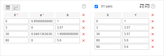
Note that the last pair of points is how the system calculated before (the fuel consumption was considered constant for a speed above 80 km/h). You cannot use this method and change the set of points. Also '3' in this example is the minimum speed from the unit's trip detector, consequently, this parameter can be different for your unit.
Result: in our example, the average consumption has been calculated for the unit. It has been calculated relative to the speed and time between messages and taking into account the values of the vehicle operation.