Fleetrun
Hecterra
NimBus
Other apps
Wialon for Android/iOS
Logistics
Wialon Local
Wialon Hosting
WiaTag
Configurator
LeaseControl
en
Contents
Unfinished Trips
  • tables
  • trips

See the Trips between geofences topic to learn how to prepare trips for this report.

A trip is considered to be unfinished when the unit leaves the starting point, and then, not having visited any of the final points, again appears in the point marked as the beginning. It can be the same zone from where the unit left (if circle trips are not allowed) or some other geofence with a starting point mark.

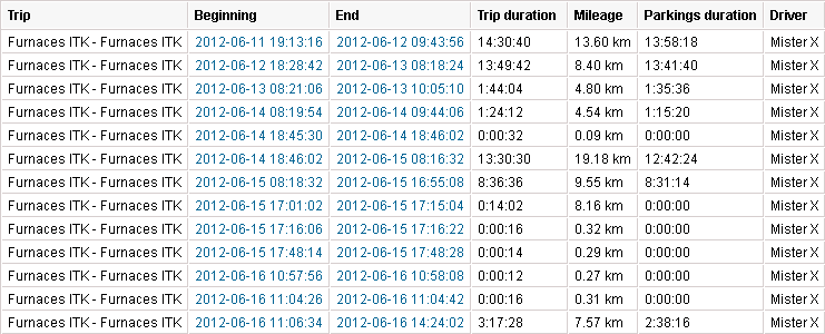
The available columns are described below.

ColumnDescription
TripThe departure and destination point.
Trip fromThe departure point.
Trip toThe destination point.
BeginningThe date and time when the trip began.
EndThe date and time when the trip ended.
MileageThe distance travelled during the trip.
Mileage (adjusted)The mileage subject to the coefficient set in the unit properties on the Advanced tab.
Trip durationThe amount of time it took to perform the trip.
Total time

The time from the beginning to the end of trip. It is recommended to use this column in combination with the grouping parameter or the Total row. If the Total row is configured in the table, it shows all the time that elapsed from the start of the first trip to the end of the last one.

Parkings durationThe time spent on parkings.
Avg speedThe average speed calculated for the trip.
Max speedThe maximum speed registered during the trip.
DriverThe name of the driver (if identified).
TrailerThe name of the trailer (if it was assigned).
CounterThe counter sensor value.
Initial counterThe value of a counter at the moment of leaving a departure geofence.
Final counterThe value of the counter at the moment of entering a destination end.
CountThe number of trips (can be helpful either when grouping the table data by years/months/weeks/days/shifts or for the reports on unit groups).
StatusThe unit status registered during the trip. It can be registered manually or automatically by means of a notification. If there are several registered statuses, the first of them is displayed.
ConsumedThe volume of consumed fuel detected by any sort of fuel sensor. If several such sensors are available, their values sum up.
Consumed by ImpFCS/AbsFCS/InsFCS/FLS/math/math for FLS/ratesThe volume of consumed fuel detected by a fuel sensor (such as impulse/absolute/instant fuel consumption sensor, fuel level sensor) or calculated by math or rates. More information on fuel in reports can be found here.
Avg consumptionThe average fuel consumption by any sort of fuel sensor. If several such sensors are available, their values sum up.
Avg consumption by ImpFCS/AbsFCS/InsFCS/FLS/math/math for FLS/ratesThe average fuel consumption during the trip detected by one of the methods mentioned above.
Initial fuel levelThe fuel level at the beginning of the trip.
Final fuel levelThe fuel level at the end of the trip.
Max fuel levelThe maximum fuel level.
Min fuel levelThe minimum fuel level.
PenaltiesThe penalties calculated for the adjusted Eco driving criteria.
RankThe received penalty points converted into a grade using a 10-point scoring system.
NotesAn empty column for your custom comments.
Video

Files saved during the trip using the Video module. To watch them, click on the icon (the number of grouped files is indicated to the right of it, if several). If several grouped files are available, you can select the required one in the drop-down list in the upper-left corner.

The column is available if the Video monitoring service is activated in the account properties.

ImageThe images received from the unit. Viewing images in reports and the functions available while doing this are described here.

See the Trips between geofences section to find out more information about the additional parameters for unfinished trips.

Questions and answers

  Reports show incorrect mileage. What should I do?

Possible explanations and actions:

1. Outliers of data.

To detect such outliers, build a track of unit movement for the appropriate period. Outliers of data will be seen on the track as dashed lines.

Ways to overcome outliers:

  • Enable filtration of unit positional information in messages (on the Advanced tab of unit properties). This will not affect old messages but applied to new ones.
  • To correct data in reports, change settings of trip detection, in particular, reduce Maximum interval between messages and increase Minimum satellites.

2. Incorrect settings or operation of the mileage counter.

  • Check the mileage counter settings on the General tab of unit properties.

  Do reports display the data on the manual assignment of the driver after the data storage period expires?

Yes, but only if the driver has not had other assignments since they were last assigned to the unit.

  What is the difference between time-based and mileage-based calculation of fuel level?

1. Mileage-based calculation

In a standard situation, all calculations of fuel level are mileage-based. That means data from the FLS is taken only during intervals of movement (trips). Those trips are defined according to parameters set in the trip detector.

Drains and fillings are detected if there is a difference between the fuel level on the following movement interval (X) and the fuel level on the previous movement interval (Y). If (X — Y) > 0, it is a filling; if (X — Y) < 0, it is a drain; if X = Y, it is neither. Of course, there can be some inaccuracy in data coming from the FLS. That is why, to avoid false drains and fillings, set the following parameters in the FLS properties:

  • minimum fuel filling volume,
  • minimum fuel drain volume,
  • minimum stop duration to detect a fuel drain,
  • and some others.

2. Time-based calculation

This type of calculation is more complicated and is based on the following algorithm: the speed of the decrease of fuel level according to the FLS is compared with the consumption calculated mathematically. The time-based calculation is necessary for stationary units. It is also widely used for moving units for controlling drains during the movement, for example.

Example

A vehicle stayed at a parking lot during 10 hours. Defueling was made in small portions over the whole parking period. As a result, 60 liters of fuel were drained. It is possible to determine if it was a drain o fuel consumption according to the state of the unit's ignition sensor. ​

  Why doesn't consumption by math work?

Since the consumption math mechanism is based on the values of the ignition sensor, check its properties and operation. You may not have this sensor created or there may be 0 l/h indicated for the fuel consumption in its properties.

  How to configure consumption by math if the unit doesn't have ignition?

You may use one of the approaches described below.

Variant 1

Create a virtual ignition sensor. We recommend that you use average speed (speed+#speed)/const2 as its parameter.

Variant 2

Even if you haven't installed an ignition sensor in the unit or are not sure of the name of the parameter that responds for the ignition, in the parameters of the device there may be some characteristic that corresponds to the operation of the engine. To use it, compare two messages from the unit: one — when the ignition the most probably off; the other — when it's on.

Example

During a long time interval the unit sends approximately the following set of parameters:

hdop=1, odo=0, adc2=2.0475, adc12=1037, c1=0, c2=0, c3=0, c4=0, mcc=260, mnc=2, lac=56720, cell_id=43811, ta=1,
gsm_lvl=55, total_fuel=407154, can_fls=101, can_taho=4797, can_engine_hrs=230420, can_mileage=137603392, engine_temp=123,
srv_dist=0, j1939_air_temp=9072, J1708_eng_hrs=230420, J1708_fl_used=430282, J1708_fl_lvl=101, I/O=80/0

While moving at some speed — approximately the following:

hdop=1, odo=847.358764648, adc2=2.3595, adc12=1117, c1=0, c2=0, c3=0, c4=0, mcc=260, mnc=2, lac=56720, cell_id=60167, 
ta=1, gsm_lvl=71, total_fuel=407178, can_fls=101, can_taho=9940, can_engine_hrs=230447, can_mileage=137609550, 
engine_temp=124, srv_dist=0, j1939_air_temp=9353, J1708_eng_hrs=230447, J1708_fl_used=430307, J1708_fl_lvl=101, I/O=d1/0

Straight before the start of the movement, as a rule, the ignition turns on:

hdop=1, odo=0, adc2=1.4937, adc12=895, c1=0, c2=0, c3=0, c4=0, mcc=260, mnc=2, lac=56720, cell_id=60268, ta=2, 
gsm_lvl=64, total_fuel=407166, can_fls=100, can_taho=996, can_engine_hrs=230439, can_mileage=137605711, engine_temp=120, 
srv_dist=0, j1939_air_temp=9369, J1708_eng_hrs=230439, J1708_fl_used=430295, J1708_fl_lvl=100, I/O=80/0

Discard the parameters that are obviously imprecise: hdop (precision), adcN (it's difficult to determine the regularity), odo (relative odometer in meters), mcc mnc cell_id and lac (LBS data section), gsm_lvl (the level of the GSM signal), etc. The parameter J1708_eng_hrs for this unit seems the most probable, as it doesn't change during the night parking. As a rule, it is also possible to use pwr_ext. Is the ignition is digital, you can follow the values' changes in the block 'I/O =' (see more details in the Inputs and outputs section).

Variant 3

If you have already connected the ignition, find out its parameter by means of the method described above or from the manual of the manufacturer.

  Why does mathematical calculation show enormous values?

Possible reasons:

  • In some cases, the system may consider that during the interval with no messages from the unit its ignition was on. Adjust the default value '0 seconds' on the Maximum interval between messages option on the Advanced tab of unit properties. The influence of the option on the fuel calculation is described in the documentation.
  • Several engine efficiency sensors can be created. Check up their values. The easiest way to evaluate it is to create in a report a simple chart with one of the curves Fuel consumption by math.
  How to determine fuel consumption, if I know how much fuel the unit consumes within the city, and how much outside it?

Let us suppose that the fuel consumption in the urban cycle is 10 l/100 km and 7 l/100 km — in the suburban cycle.

  • Create an ignition sensor (as in the example above) and set 1 l/h for the consumption during idling.
  • The average consumption in the urban cycle is 36 km/h, in the suburban — 80 km/h.
  • The unit will cover a distance of 100 km driving at a speed of 36 km/h in 2.8 hours. 10 l / 2.8 = 3.57. Let us calculate the value of the increasing coefficient when moving in the city: 3.57 / 1 (idling) = 3.57.
  • As a result of a similar calculation for the suburban cycle, we obtain the coefficient equal to 5.6.
  • Create an engine efficiency sensor, taking into account the fact that the unit cannot consume less fuel than during the idling, and that it is stationary before the beginning of the movement. As a parameter we use the average speed (speed + # speed) / const2 and fill in the calculation table (manually or using the calculation table wizard):

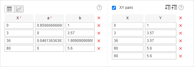
Note that the last pair of points is how the system calculated before (the fuel consumption was considered constant for a speed above 80 km/h). You cannot use this method and change the set of points. Also '3' in this example is the minimum speed from the unit's trip detector, consequently, this parameter can be different for your unit.

Result: in our example, the average consumption has been calculated for the unit. It has been calculated relative to the speed and time between messages and taking into account the values of the vehicle operation.

  How does the mathematical calculation algorithm work?

During the mathematical calculation, fuel consumption is computed separately for each pair of messages.

The following algorithm is used:

  1. The status of each engine sensor (engine ignition, absolute and relative engine hours sensors) in the current message is determined.
  2. For the operating sensors the values indicated in the field Consumed, l/h of their properties are summed.
  3. The values of the engine efficiency sensors bounded to the engine sensors are calculated.
  4. The received values are summed according to the formula k1 + (k2 - 1) + (k3 - 1) + … + (kn – 1). In that way, the coefficient is formed. If the sum of the coefficients is less than 0 or invalid, the total coefficient will be 1.
  5. To determine the current fuel consumption of the unit, the value from point 2 is multiplied by the value of point 4.
  6. The value from the previous message till the current one is multiplied by the value from point 5.
  7. The consumption for each message pair for the indicated interval is summed and in that way, the fuel consumption is determined by consumption math.

If you find a mistake in the text, please select it and press Ctrl+Enter.
Thank you for your feedback!
Report a mistake
Text with the mistake Comment
Maximum 500 characters