Sensors: Logic and alternatives to validation
One of the first and crucial stages of working with Wialon is setting up sensors in the unit. This article will provide a detailed explanation of sensor validation, as it has some non-obvious use cases and allows users to perform unique actions with sensors.
General principle of sensors operation
Wialon supports many types of trackers; you can find their current number on the wialon.com website in the Hardware section. Each of the trackers “speaks” in its own way. Therefore, the parameters which come from different types of trackers and which are displayed on the Messages tab may contain the same information (for example, about temperature or mileage) but have different names. It is necessary to create sensors for each unit in Wialon to prevent users from noticing the differences when using units with various trackers. Also, sensors have a specific type, which allows the system to understand which algorithm to choose to process input values.
However, a simple selection of a sensor type and specifying a parameter in it is often not enough because the parameter value comes in an unobvious to the user way. There are three methods to convert the input parameter to the desired type:
- Expression in the Parameter field;
- Calculation table;
- Validation.
They can be used individually or combined. If you use several methods simultaneously, they will be applied in the exact order they are listed above.
In some cases, the same result can be achieved using different methods. For example, summing the values of two sensors can be done using both an expression in the Parameter field and validation. Similar cases will be considered further.
When to use validation
Validation is used in cases where it is necessary to link the value of one sensor to another. In terms of practical applications, the following cases can be distinguished for using validation:
- one sensor affects another at the physical level (for example, a fuel level sensor shows the wrong value when there is a jump in the voltage sensor readings);
- it is necessary to link several sensors into a logical scheme (for example, it is necessary to create a sensor for opening the front doors of a car, which will be activated when either the left door opening sensor or the right door opening sensor is on);
- it is necessary to display a report for a time interval, where an old sensor with one parameter was used at the beginning and a new sensor with another parameter was used at the end (for example, a less accurate fuel level sensor with one calibration table was previously used on a truck and then it was replaced with a more accurate fuel level sensor with another calibration table);
- several sensors are measuring the same parameter and it is necessary to display the value of one or the other sensor (for example, a more accurate fuel level sensor was installed on a vehicle in addition to a less accurate factory-installed fuel level sensor, and usually the readings of the more accurate one are used, but if they have an error, it is better to read the values of the factory-installed sensor, even though they are less accurate);
- the parameter contains information about different systems of a unit, and only a certain part needs to be extracted from it (for example, the first 5 bits of the parameter indicate voltage, while the subsequent bits have a different purpose, and only those bits related to voltage are to be extracted from the parameter);
- some arithmetic calculations need to be performed that involve values from several sensors (for example, it is necessary to see the real-time fuel consumption in km/l, which is calculated by dividing the reading from the relative odometer by the reading from the instant fuel consumption sensor).
Types of validation
There are 12 types of validation in Wialon. You won’t see such a division in the monitoring system interface, but for simplicity, all types can be roughly divided into 3 groups.
| Group | Validation types | Comment | Alternatives |
|---|---|---|---|
| Arithmetic | Sum up Subtract validator from sensor Subtract sensor from validator Multiply Divide sensor by validator Divide validator by sensor |
You can easily work without these types. | Alternatives exist and are simple. |
| Algorithmic | Not-null check Replace sensor with validator in case of error |
Both types are used frequently. | There is a simple alternative for the second type. |
| Logical | Logical AND Logical OR Math AND Math OR |
The least clear types, usually only the first two are used. | Alternatives exist, but they are not simple. |
Let’s consider each group in more detail.
Arithmetic validation
This group includes basic arithmetic operations: addition, subtraction, multiplication, and division.
You can easily work without these types of validation, as similar results can be achieved using an expression in the Parameter field. To refer to the value of another sensor in the expression, you need to specify the name of this sensor in the square brackets (for example, [Fuel Level]).
The following example illustrates a small difference between these approaches.
Example
Let’s suppose messages are received from a unit with the following parameters:
- odometer, which displays the distance in kilometers traveled between the last two messages;
- fuel_consumption, which displays the fuel in liters spent between the last two messages.
The client needs a sensor that will show real-time consumption in km/l.
Here is the solution using validation:
- Create an Instant fuel consumption sensor named InsFCS based on the fuel_consumption parameter.
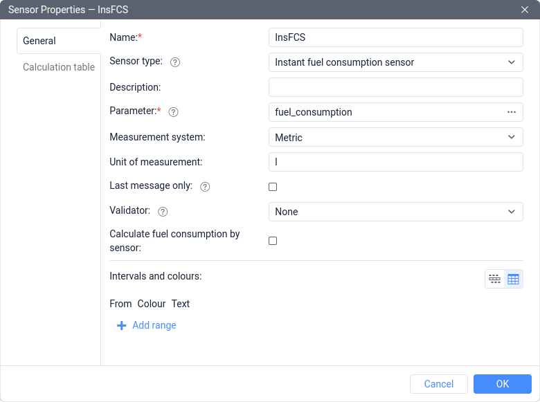
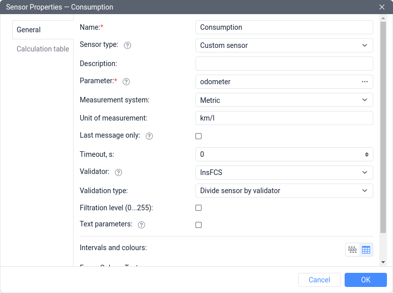
- Create a Custom sensor named Consumption with km/l as a unit of measurement. Specify the odometer as a parameter. In the properties of the Consumption sensor, specify the InsFCS sensor as a validator and choose the Divide sensor by validator validation type.
The solution using an expression:
- Create a sensor with the Relative odometer type named Relative mileage based on the odometer parameter.
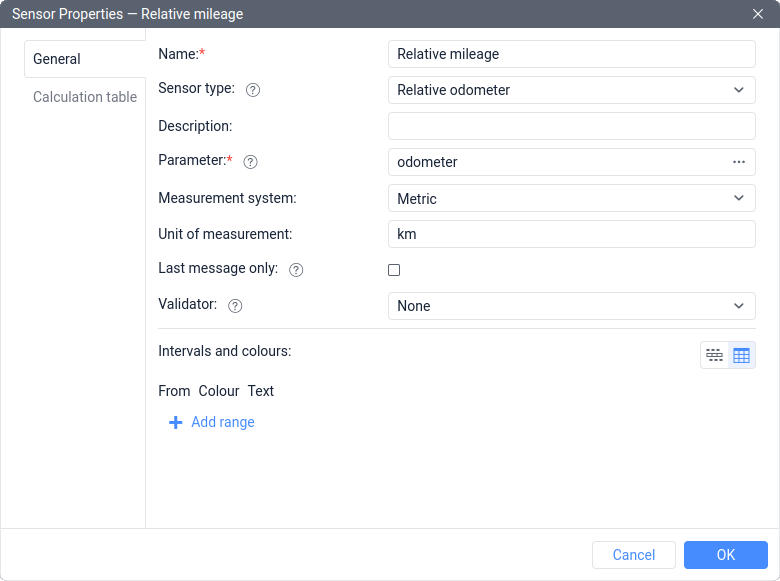
- Create an Instant fuel consumption sensor named InsFCS based on the fuel_consumption parameter.
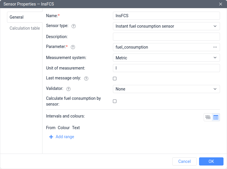
- Create a Custom sensor named Consumption with km/l as a unit of measurement. Use a formula with the names of the previously created sensors in square brackets: [Relative mileage]/[InsFCS].
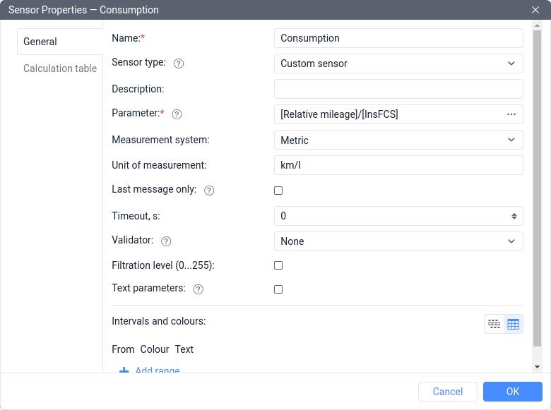
As you can see, when using validation, it is enough to create 2 sensors, not 3. In this case, however, none of the sensors will show the mileage value between messages. Nevertheless, if you need to create a sensor with the Relative odometer type for solving other tasks, then the solution using an expression will be more convenient.
Algorithmic validation
This group includes only 2 types of validation, and we will consider each of them.
Not-null check
This type of validation is one of the most commonly used. It allows ignoring incorrect readings of the validated sensor, while their availability is determined by the zero value of the validating sensor (the validator).
The most common situation of application is as follows: a sensor connected to the tracker may show incorrect data when the voltage is insufficient.
Example
Let’s suppose the following sensors are created in the unit:
- Fuel level sensor named FLS, which is based on the parameter fuel_lvl;
- The Voltage sensor named Voltage, which is based on the parameter pwr_ext.
When the voltage value drops below 9 volts, an analog fuel level sensor shows incorrect values. To control fuel properly, it is necessary to get rid of false readings.
In this case, it is necessary to follow the next steps:
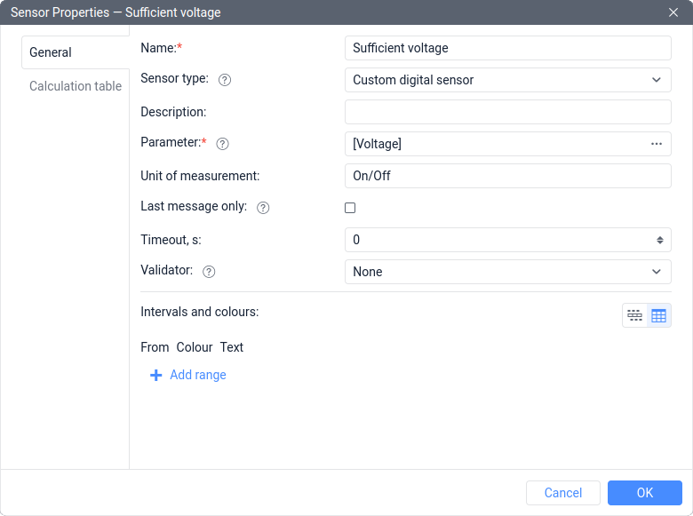
- Create a Custom digital sensor named Sufficient voltage based on the [Voltage] expression.
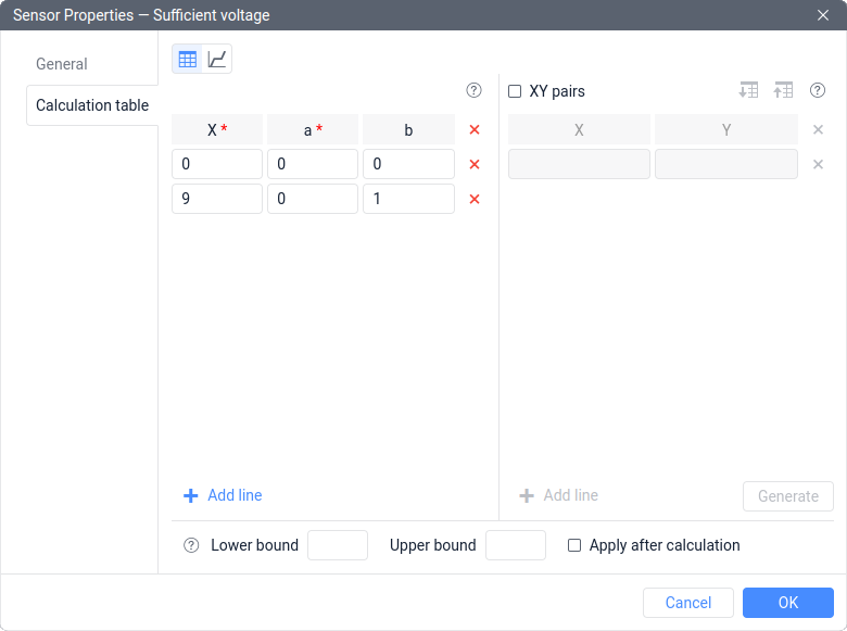
- Add a calculation table with the following rows:
X=0; a=0; b=0
X=9; a=0; b=1
- In the properties of FLS, specify the Sufficient voltage sensor as a validator and select Not-null check as the type of validation.
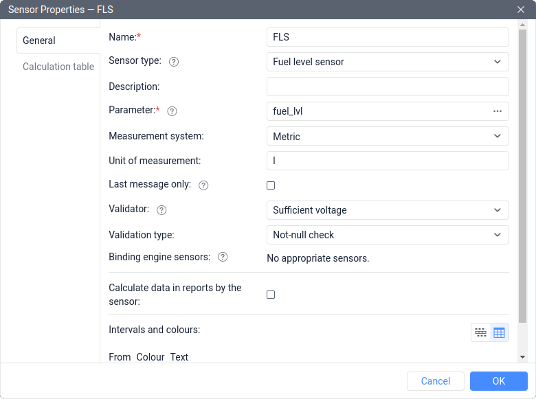
Now, when the voltage drops below 9 volts, the Sufficient voltage sensor will have a value of 0 (Off), therefore, the not-null check will not be passed, so the FLS readings will be replaced with a dash (N/A). This will exclude incorrect data from the analysis.
The use of the Not-null check validation is possible not only in situations where sensors are physically linked to each other (in the example above, the operation of the sensor is affected by insufficient voltage), but also in cases where there is a correlation between sensor values. For example, if you notice that for some reason FLS shows false values when the temperature sensor shows a value of 255, this is enough to use this type of validation.
Replacing the sensor with a validator in case of an error
This type of validation is also quite popular. Its logic is simple: if the validated sensor has an erroneous value, it is replaced with the value of the validator.
This is the only type of validation that can react to erroneous sensor values, which are displayed as a dash or N/A. All the other types of validation will display an error both on input and output.
This type is suitable for situations where it is necessary to display the value of two sensors as if they were one sensor. There are usually two reasons for this: either an old sensor has been replaced with a new one, and reports should contain information for both the old and new sensor intervals, or there are two sensors on the unit at the same time, but one of them occasionally displays an error, and at this moment it is necessary to display the value of the other sensor. Let’s consider both cases with examples.
Example 1
Let’s suppose that messages with the following parameters were received from the unit within the reporting interval:
- adc1, which displays the fuel level in volts according to the previously installed fuel level sensor (the parameter is missing in new messages);
- param4, which displays the fuel level in volts according to the new fuel level sensor (the parameter is missing in old messages).
It is necessary to set up the sensors so that the report can display data on fuel from both old and new sensors.
In such a case, follow these steps:
- Create a Fuel level sensor named FLS (old) based on the adc1 parameter. It is necessary to enter the old calibration table into the FLS (old) calculation table to convert volts to liters.
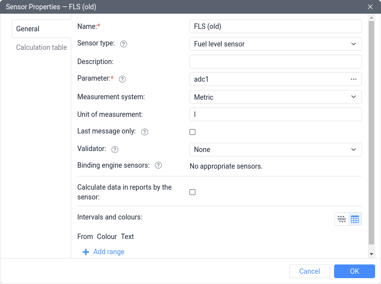
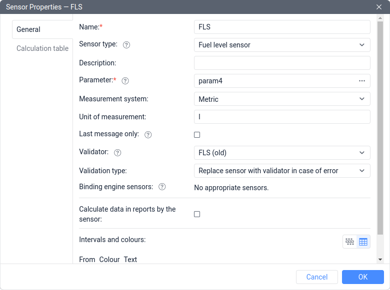
- Create a Fuel level sensor named FLS based on the param4 parameter. It is necessary to enter the new calibration table into its calculation table to convert volts to liters. In the properties of FLS, specify the FLS (old) sensor as a validator and select the Replace sensor with validator in case of error as a type of validation.
This task can be solved using an expression in the Parameter field, namely using the Value availability check operation. To do this:
- Create a Fuel level sensor named FLS (old) based on the adc1 parameter. It is necessary to enter the old calibration table into its calculation table to convert volts to liters.
- Create a Fuel level sensor named FLS based on the param4|[FLS (old)]. It is necessary to enter the new calibration table into its calculation table to convert volts to liters.
Example 2
Let’s suppose that messages are received from the unit containing the following parameters:
- fls_rs485, which displays the fuel level in volts according to the installed fuel level sensor;
- fuel_lvl, which displays the fuel level in liters according to the factory-installed fuel level sensor.
The installed FLS is more accurate, but sometimes it displays an error, and once it happens, the client wants to see the readings of the factory-installed FLS.
In this case, it is necessary to follow the next steps:
- Create a Custom sensor named Factory-installed FLS based on the fuel_lvl parameter.
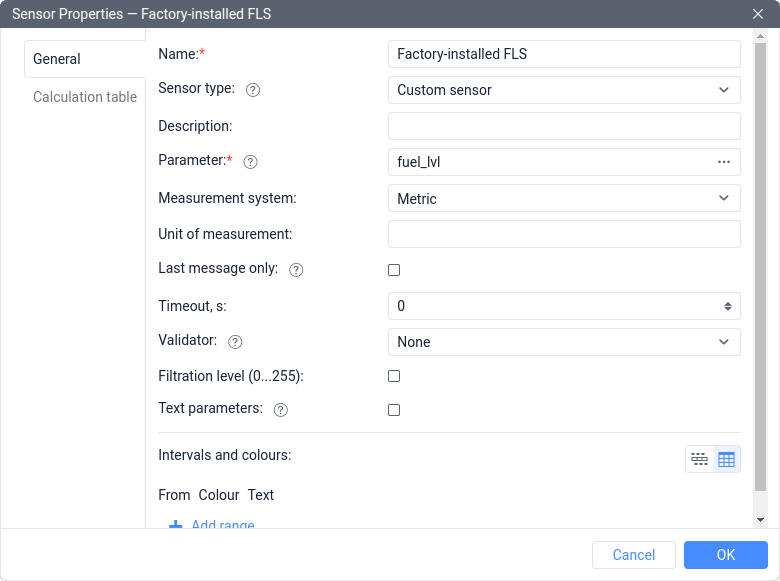
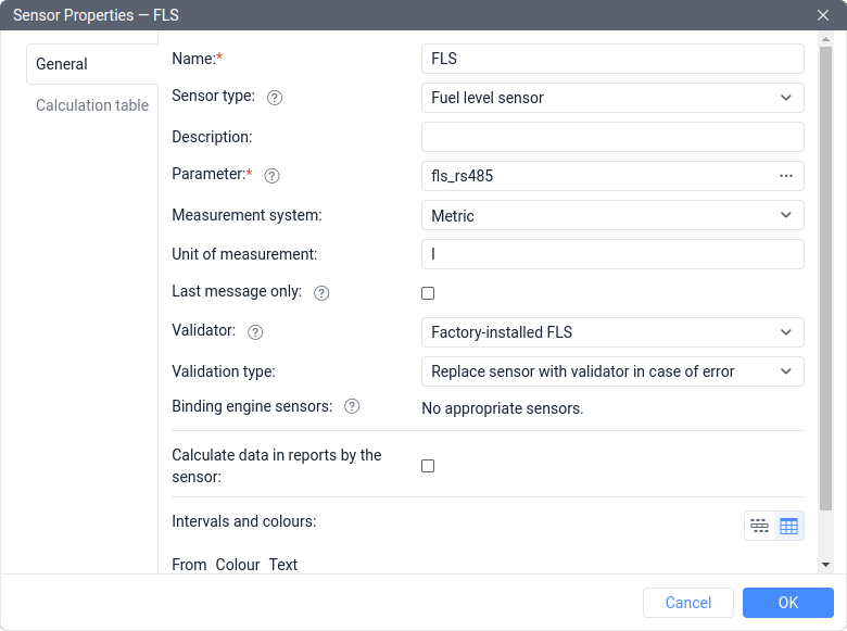
- Create a Fuel level sensor named FLS based on the fls_rs485 parameter. It is necessary to enter a calibration table into the FLS calculation table to convert volts to liters. In the properties of FLS, specify the Factory-installed FLS sensor as a validator and select Replace sensor with validator in case of error as the type of validation.
Logical validation
This group includes 4 types of validation:
- Logical AND and Logical OR, which work with logical values (in Wialon they are called digital, that is, On/Off or 1/0);
- Math AND and Math OR, which work separately with each bit of numbers.
Let’s consider these types with examples.
Logical AND/OR
For simplicity, the Logical AND operation gives a value of 1 as a result only when both input values are equal to 1, and the Logical OR gives a value of 1 if at least one of the input values is equal to 1.
If we assume that two sensors are linked by validation, and one of them is based on parameter a, and the other is based on parameter b, then all possible results can be described using one table:
| a | b | a AND b | a OR b |
|---|---|---|---|
| 0 | 0 | 0 | 0 |
| 0 | 1 | 0 | 1 |
| 1 | 0 | 0 | 1 |
| 1 | 1 | 1 | 1 |
After performing logical AND/OR operations, the value of the validated sensor will always be equal to 0 or 1 (in this case, an error is not considered, i.e., it’s going to be a dash or N/A).
Only values of 0 or 1 are also expected at the input. However, in Wialon, there may be a situation where other numerical values are input for validation. In this case, the system will operate as follows:
- Only 0 is perceived as 0 (Off).
- Any other numerical value (for example, 0.01, -0.01, 100500, -777, etc.) will be perceived as 1 (On).
Ideally, it is worth avoiding such situations and using a calculation table to convert all incoming values to only 0 or 1.
Example 1
Let’s suppose that messages are coming from a unit containing the following parameters:
- in3, which equals 0 when the attachment equipment is turned off, or 1 when it is turned on;
- in4, which equals 0 when the rear door is closed, or 1 when it is open.
It is necessary to create a sensor that will be activated when the attachment equipment is on and the rear door is open.
In this case, it is necessary to do the following steps:
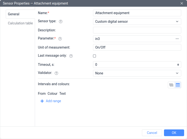
- Create a Custom digital sensor named Attachment equipment, based on parameter in3.
- Create a Custom digital sensor named Rear door is open when the equipment is on based on parameter in4. Then select the Attachment equipment sensor as the validator and choose the Logical AND validation type.
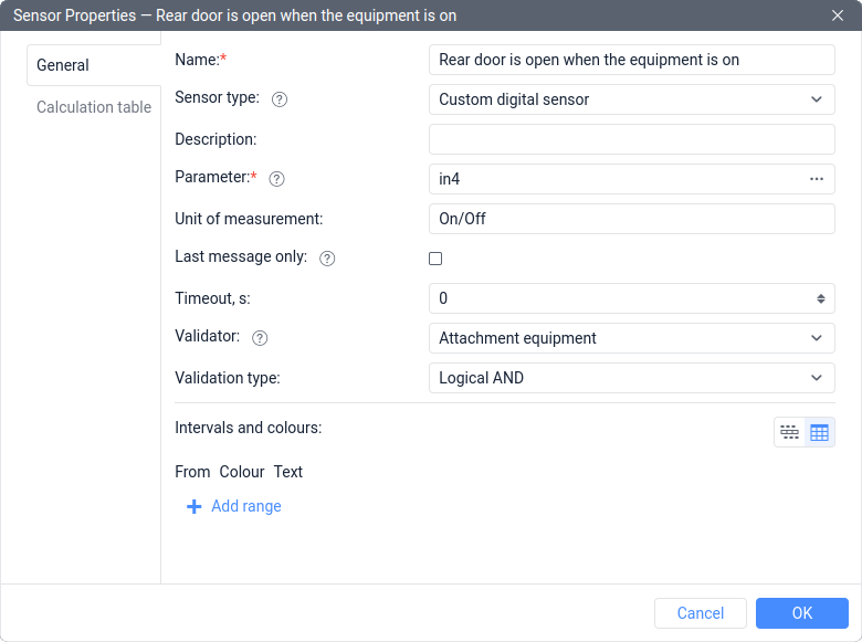
This problem can also be solved using an expression in the Parameter field. To do this, it is enough to create a Custom digital sensor named Rear door is open when the equipment is on based on the expression in3*in4.
This approach will work if the parameters can only have values of 0 or 1.
Example 2
Let’s suppose that messages are coming from a unit containing the following parameters:
- door11, which equals 0 when the left front door is closed, or 1 when this door is open;
- door12, which equals 0 when the right front door is closed, or 1 when this door is open.
It is necessary to create a sensor that will be activated when at least one of the front doors of the car is open.
In this case, follow these steps:
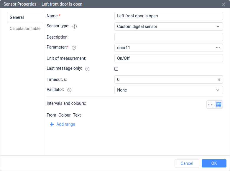
- Create a Custom digital sensor named Left front door is open, based on parameter door11.
- Create a Custom digital sensor named Front doors are open, based on parameter door12. Then specify the Left front door is open sensor as the validator and choose the Logical OR validation type.
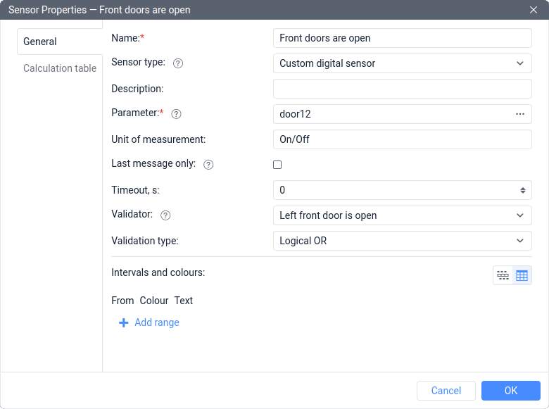
This task can also be solved using an expression in the Parameter field and a calculation table:
- Create a Custom digital sensor named Front doors are open based on the expression door11+door12.
- Add a calculation table to the sensor with the following rows:
X=0; a=0; b=0
X=1; a=0; b=1
This approach will work if the parameters can only have values of 0 or 1.
Math AND
This validation is useful for extracting a specific part of the bits from a parameter. It involves bitwise execution of the Logical AND operation, as demonstrated below.
First, convert the considered number must be from decimal (DEC) to binary (BIN) numeral system using the Calculator application in programmer mode or similar online tools.
For example, the result of the math AND between the numbers 122 and 15 will look like this:
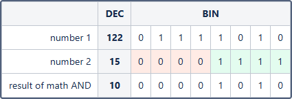
If the bit in the second number is equal to 0 (highlighted in red), then the final value of this bit will also be 0. If the bit in the second number is equal to 1 (highlighted in green), then the final value of this bit will be equal to the value of the bit in the first number. We can say that using the binary representation of the number 15, the number 122 was filtered in such a way as to leave only the 4 least significant bits in it.
Example 1
Let’s suppose that we receive messages from the unit with a 16-bit parameter can_a1 that contains information about different systems of the unit. Based on the tracker documentation, information about the fuel level is contained in the 8 least significant bits of the parameter. It is necessary to verify this and extract part of the parameter from the 8 least significant bits to create a fuel level sensor based on them.
For example, when a 100-liter tank is filled up to 40%, the value of the parameter can_a1 may have the following values:
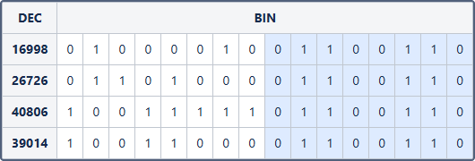
As you can see, the value of the parameter can_a1 can change in decimal representation. But at the same time, the 8 least significant bits of the parameter remain unchanged (they are highlighted in blue), as the amount of fuel in the tank does not change. If we convert the values of the 8 least significant bits into decimal, we get:
(BIN) 0110 0110 = (DEC) 102
The maximum value that can be stored in 8 bits is:
(BIN) 1111 1111 = (DEC) 255
Using simple arithmetic operations, we verify that 102/255 = 40/100 = 0.4. This brings us to the conclusion that the 8 least significant bits of the parameter indeed correspond to a tank filled up to 40%.
To extract the first part of the parameter, you need to follow these steps:
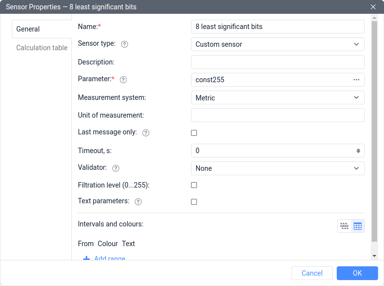
- Create a Custom sensor named 8 least significant bits based on the const255 parameter.
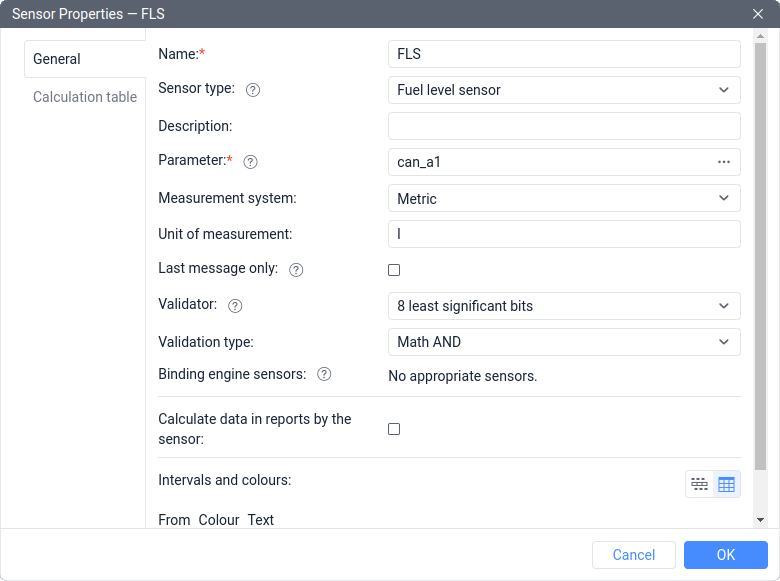
- Create a Fuel level sensor named FLS based on the can_a1 parameter. Then select the 8 least significant bits sensor as a validator and choose Math AND validation type. Also, it is necessary to enter a calibration table into the sensor calculation table to convert the result into liters.
Since each bit can have different values in different messages, let’s label the least significant bits as b and the most significant ones as B:

As a result, using the binary representation of the number 255, the can_a1 parameter was filtered in such a way as to leave only the 8 least significant bits in it.
This task can be solved using an expression in the Parameter field.
To do this, create a Fuel level sensor named FLS based on the following expression:
**const128*can_a1:8+const64*can_a1:7+const32*can_a1:6+const16*can_a1:5+const8*can_a1:4+
const4*can_a1:3+const2*can_a1:2+const1*can_a1:1
**More details about such a solution can be found in the article about working with bits.
Example 2
Let’s suppose that we receive messages from the unit with a 16-bit parameter can_b2 that contains information about different systems of the unit. Based to the tracker documentation, information about the fuel level is contained in the 8 most significant bits of the parameter. It is necessary to verify this and extract part of the parameter from the 8 most significant bits to create a fuel level sensor based on them.
For example, when a 200-liter tank is filled up to 60%, the value of the parameter can_b2 may have the following values:
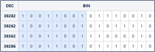
As you can see, the value of the parameter can_b2 can change in decimal representation. But at the same time, the 8 most significant bits of the parameter remain unchanged (they are highlighted in blue), as the amount of fuel in the tank does not change. If we convert the values of the 8 most significant bits into decimal, we get:
(BIN) 1001 1001 = (DEC) 153
The maximum value that can be stored in 8 bits is:
(BIN) 1111 1111 = (DEC) 255
Using simple arithmetic operations, we verify that 153/255 = 120/200 = 0.6. This brings us to the conclusion that the 8 most significant bits of the parameter indeed correspond to a tank filled up to 60%.
To extract the second part of the parameter, it is necessary to do the following:
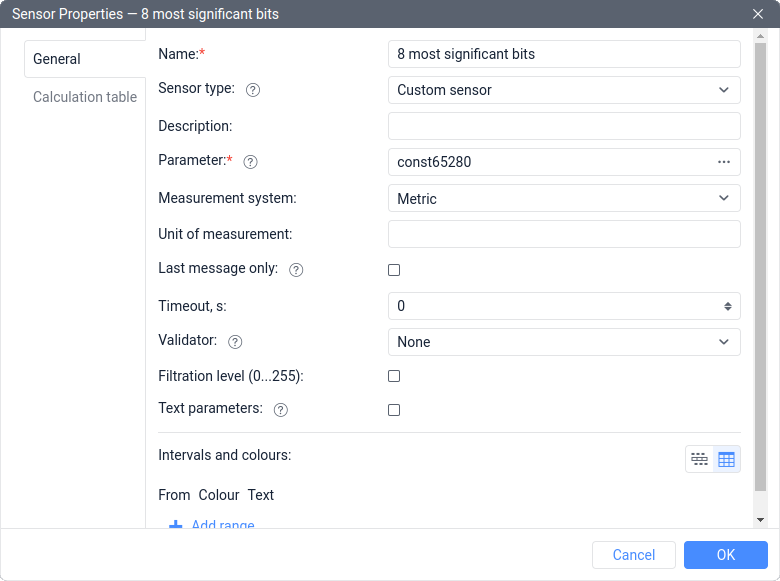
- Create a Custom sensor named 8 most significant bits based on the parameter const65280.
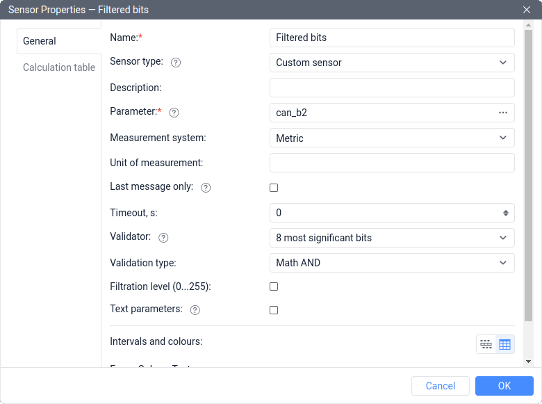
- Create a Custom sensor named Filtered bits based on the parameter can_b2. Then select the 8 most significant bits sensor as a validator and select the Math AND validation type.
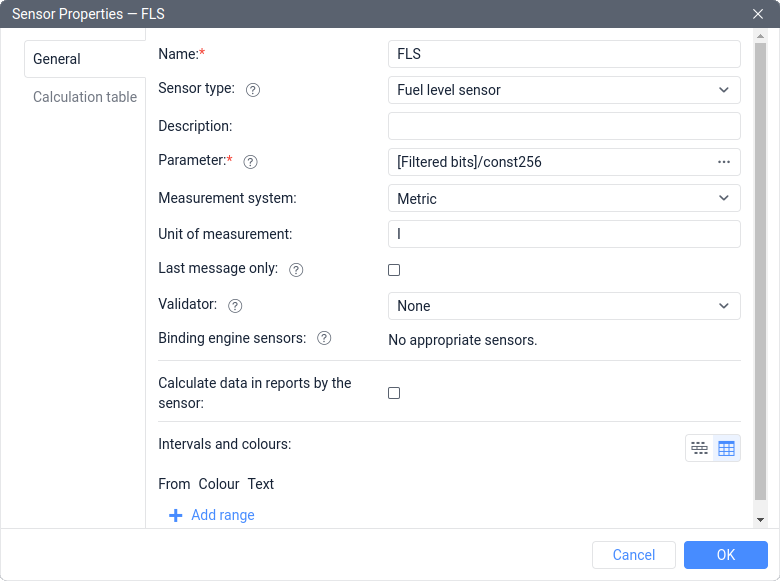
- Create a Fuel level sensor named FLS based on the expression [Filtered bits]/const256. It is necessary to enter a calibration table into its calculation table to convert the result into liters.
Since each bit can have different values in different messages, let’s label the least significant bits as b and the most significant ones as B:

Shifting bits down by several digits occurs through division by 2 to the power, which is equal to the number of digits to shift. In this case, we need an offset by 8 digits, so division is carried out by 28 = 256.
As a result, using the binary representation of the number 65280, the can_b2 parameter was filtered in such a way as to leave only the 8 most significant bits in it, and then they were converted into the least significant bits using the offset.
This task can be solved using an expression in the Parameter field.
To do this, create a Fuel level sensor named FLS based on the following expression:
const128*can_b2:16+const64*can_b2:15+const32*can_b2:14+const16*can_b2:13+const8*can_b2:12+
const4*can_b2:11+const2*can_b2:10+const1*can_b2:9
More details about such a solution can be found in the article about working with bits.
Math OR
This validation implies bitwise execution of the Logical OR operation, as demonstrated below.
First, convert the considered number must be from decimal (DEC) to binary (BIN) numeral system using the Calculator application in programmer mode or similar online tools.
For example, the result of the math OR between the numbers 122 and 210 will look like this:
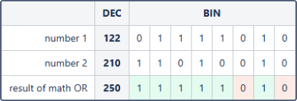
If at least one of the bits in the first two numbers is equal to 1, then the final value of this bit will be equal to 1 (highlighted in green). If both bits in the first two numbers are equal to 0, then the final value of this bit will be equal to 0 (highlighted in red).
