General properties
The window of sensor properties, which opens when creating, editing, or copying a sensor, consists of the General and Calculation table tabs.
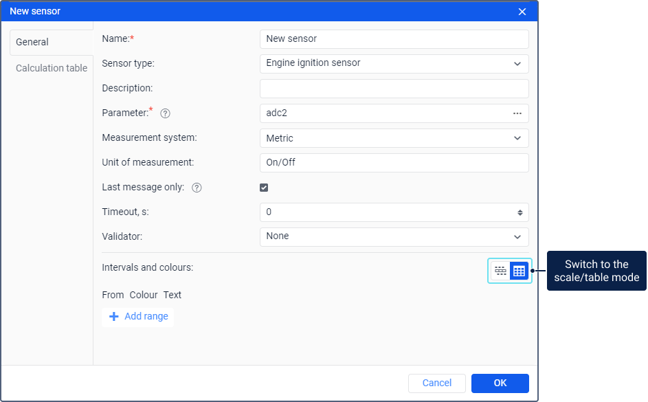
On the General tab, you can specify the name and parameter of the sensor, configure colors for sensor value intervals, and so on. The table below describes the fields available on the tab. The required fields are marked with an asterisk (*).
Some fields are shown only for certain sensor types. For example, the Filtering level field is shown for the custom sensor, temperature sensor, and weight sensor, and the Text parameters field is shown only for the custom sensor.
| Field | Description |
|---|---|
| Name* | The name of the sensor in the system. |
| Sensor type | The type of the sensor. Select it in accordance with the principle of the sensor operation and the equipment used. The sensor type should correspond to the characteristics of the device used for the unit, otherwise, the calculations can be incorrect. The list shows only those types for which the corresponding service is enabled in the billing plan or account properties. See the description of all types on the Sensor types page. |
| Description | Additional information about the sensor. This information is shown in the sensor table on the Sensors tab in the unit properties. |
| Parameter* | The parameter the values of which are sent by the device and which should be used for the sensor being created. You can select the parameter in the drop-down list or enter it manually. You can specify it in the form of an expression using several parameters in the field. |
| Measurement system | The measurement system in which the sensor values should be received. |
| Unit of measurement | The unit of measurement in which the sensor values are displayed in the system: in reports, jobs, tooltips, and so on. For custom sensors, you can specify any unit of measurement. For ignition sensors, you can edit the units of measurement. For example, instead of On/Off, you can specify Activated/Deactivated, Enabled/Disabled, and so on. |
| Last message only | The option which, when enabled, allows calculating the sensor value in the unit tooltip and other places only based on the last message. If the last message doesn’t contain the required data, Unknown is displayed instead of the value. If the option is disabled, the sensor value is calculated based on the last value of the parameter, regardless of how long ago it was received. In this case, the calculation may take up to 1 minute. |
| Timeout, s | The Timeout option is applied only to historical data (reports). The option is used to search for invalid intervals during the sensor operation. If an interval between two messages with sensor data is longer than the value indicated for the Timeout option, the interval is considered invalid and is removed from the report. In this case, the message before the invalid interval becomes the end of one interval and the message after the invalid interval becomes the beginning of the next one. You can specify the timeout for the following sensor types: engine ignition sensor, real-time motion sensor, custom sensor, and custom digital sensor. The timeout is specified in seconds.If you specify 0 in the field or leave it blank, the option is considered disabled. Example. Suppose that data messages from a sensor were received at 22:00, 22:30, 07:30 and 08:00. If the Timeout option is disabled, the report shows one continuous interval from 22:00 to 08:00. If you specify a timeout of 1 hour (3600 s), several intervals are formed. Since the difference between the first and second messages is less than an hour, they form the first interval (from 22:00 to 22:30). The difference between the second and third messages is more than an hour, therefore this interval (from 22:30 to 07:30) is considered invalid and is not taken into account. The difference between the third and fourth messages is less than an hour, therefore they form the second interval (from 07:30 to 08:00).  |
| Validator | The sensor which is used to convert the values of the main sensor. After selecting a sensor in the list, in the Validation type field, you should select the operation which should be applied to the values of the main sensor and the validation sensor. |
| Validate separation | This option is available only for the driver assignment sensor. If the option is enabled, a driver assigned to the unit can be separated from it automatically only if an empty value or a separation code comes from the same parameter as the one used for assigning the driver. If the option is disabled, the empty value or the separation code received from any sensor leads to the separation of all the drivers assigned to the unit. |
| Separation code | This option is available only for the driver assignment sensor. In the field, you can type a custom code. If the code is specified, the driver separation is carried out when an empty value or a separation code is received.Only text or integer parameter values (including after conversion) can be used as a separation code. In other cases, the sensor value is rounded and automatic separation doesn’t work. A number consisting of many characters can be indicated as a separation code if a long or text parameter which isn’t an expression is selected for the sensor without applying the calculation table. |
| Filtering level | This option allows applying the smoothing algorithm to the sensor values. In the field, indicate the level of such smoothing: from 0 to 255. The filtering level is indicated individually for each sensor.The filtering level is taken into account only in report tables. You can indicate the filtering level for the following sensor types: custom sensor, temperature sensor, and weight sensor. |
| Text parameters | This option is available only for custom sensors. Activate it if the sensor sends text parameters instead of numeric ones. In this case, in the table of intervals and colors, you can list these parameters and give them broader descriptions. For example, a device sends the parameters error1, error2, error3, and so on. In accordance with the documentation for the device, you can specify a description for each parameter (for example, Power supply disconnected, Invalid data, and so on). You can also use the special character * (asterisk) which substitutes for any combination of characters. For example, you can indicate that the value error* should always be displayed as Error. |
Intervals and colors
In this section, you can create sensor value intervals, select a color, and specify a caption for each interval.
If the sensor sends values less than the one specified in the first interval, then these values are considered part of the first interval and are highlighted in its color.
By default, all the sensors have one infinite interval (from -∞ to +∞) colored in black.
Creating intervals
The intervals on the tab are displayed in two modes:
- in the scale mode;
- in the table mode.
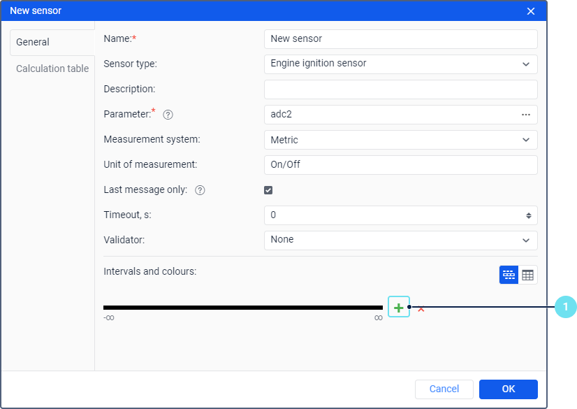
To create intervals in the scale mode, follow these steps:
-
Click on the scale or the icon
 .
.
-
In the Interval field, specify the interval beginning and end. If the first field is not filled in, its value corresponds to -∞. If the second field is not filled in, its value corresponds to +∞.
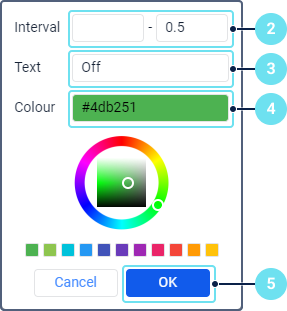
-
In the Text field, enter a caption for the interval.
-
Select a color using the palette, spectrum, or Hex format.
-
Click OK.
-
Follow steps 1–5 for the required number of intervals.
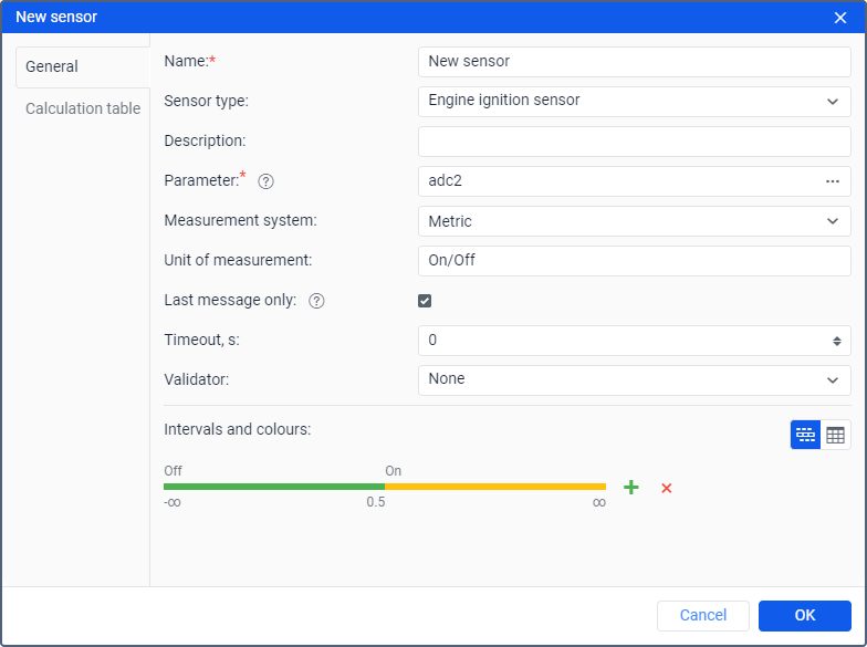
To edit an interval, click on it and specify new values. To delete all intervals, click on the icon  .
.
If you create more than 10 intervals in the scale mode, it switches to the table mode automatically.
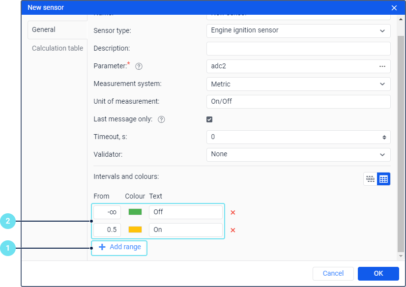
To create intervals in the table mode, follow these steps:
-
Click on the Add range button.
-
In the From field, enter the initial value of the first interval, select a color for it, and specify a caption. If the From field is empty, it is considered that -∞ is specified there.
-
Follow steps 1–2 for the required number of intervals.
To delete an interval, click on the icon .
Using intervals
The created intervals (their colors and captions) can be used in the following places of the monitoring system:
-
Sensor state option in the work list on the Monitoring tab;
-
unit tracks on the map, which you can create on the Tracks, Reports, and Monitoring tabs;
-
visualization of the unit on the map according to the last value of the sensor if you use motion state signs instead of the unit icon;
In the first three cases, you should go to the Advanced tab of the unit properties and select a sensor which should be used for these interface elements.