Advanced properties
The Advanced tab consists of several sections. In these sections, you can configure parameters for reports, track and sensor colors, filtering of unit messages, etc.
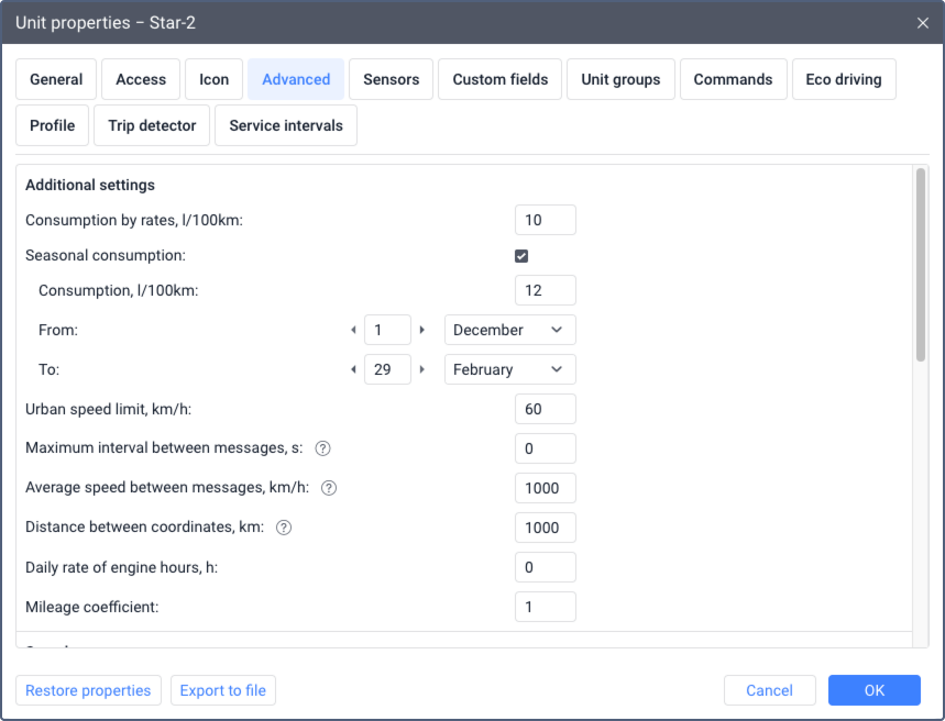
Additional settings
The parameters available in this section influence the calculations of fuel consumption, mileage, engine hours and other data.
| Parameter | Description |
|---|---|
| Consumption by rates | Fuel consumption per 100 kilometers. Another unit of measurement can be used, depending on the selected measurement system. The default value is 0. |
| Seasonal consumption | The option which allows you to specify a separate fuel consumption rate for a certain period. The default value is 0.If the Seasonal consumption option is activated, then when you create a new sensor using the math consumption wizard, the Seasonal coefficient, % option is activated there by default. The value of the coefficient is calculated in accordance with the values specified on the Advanced tab. |
| Urban speed limit | The maximum speed at which it is conventionally considered that the unit is moving within the city. Moving at a higher speed is considered as suburban mileage. You can use this setting in reports: in the Trips table, in statistics, in the advanced report on drivers. |
| Maximum interval between messages | The maximum interval between messages in seconds. If the time difference between two messages exceeds the specified value, such a time interval is considered a connection loss. You can view the intervals of no connection in the Connection problems report. The option can affect: When determining engine hour intervals, the option is used if its value is smaller than the value specified for the Timeout option of the sensor. When determining fuel filling and drain intervals, the option is used if its value is smaller than the value of the Minimum parking time option.
The default value is 0 (option disabled). |
| Average speed between messages | This option is used to exclude coordinate outliers when calculating mileage. Maximum average speed of the unit determined by two successive messages, in km/h. If the specified value is exceeded, these messages are not taken into account when calculating the mileage in reports, in the GPS and GPS + engine ignition sensor mileage counter and on the Messages tab. To disable the option, specify 0. |
| Distance between coordinates | This option is used to exclude coordinate outliers when calculating mileage. Maximum distance between coordinates in two successive messages, in km. If the specified value is exceeded, these messages are not taken into account when calculating the mileage in reports, in the GPS and GPS + engine ignition sensor mileage counter and in the Messages tab. To disable the option, specify 0. |
| Daily rate of engine hours | The daily rate of engine hours (in hours). This value can be used in the report on engine hours (when calculating utilization and useful utilization). The operation of engine hours is determined by the engine hours counter. |
| Mileage coefficient | The coefficient used to correct the mileage calculated in Wialon in cases where it always differs from the actual mileage by a certain number of times. Example. The mileage calculated in Wialon is 100 km, and the actual mileage (determined by the vehicle equipment) is 120 km. The mileage coefficient that should be specified in this field is 120/100 = 1.2. The result of multiplication by the coefficient is shown in the Mileage (adjusted) column in different report tables and statistics. |
Questions and answers
How to determine fuel consumption, if I know how much fuel the unit consumes within the city, and how much outside it?
Let us suppose that the fuel consumption in the urban cycle is 10 l/100 km and 7 l/100 km — in the suburban cycle.
- Create an ignition sensor (as in the example above) and set 1 l/h for the consumption during idling.
- The average consumption in the urban cycle is 36 km/h, in the suburban — 80 km/h.
- The unit will cover a distance of 100 km driving at a speed of 36 km/h in 2.8 hours. 10 l / 2.8 = 3.57. Let us calculate the value of the increasing coefficient when moving in the city: 3.57 / 1 (idling) = 3.57.
- As a result of a similar calculation for the suburban cycle, we obtain the coefficient equal to 5.6.
- Create an engine efficiency sensor, taking into account the fact that the unit cannot consume less fuel than during the idling, and that it is stationary before the beginning of the movement. As a parameter we use the average speed (speed + # speed) / const2 and fill in the calculation table (manually or using the calculation table wizard):
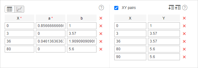
Note that the last pair of points is how the system calculated before (the fuel consumption was considered constant for a speed above 80 km/h). You cannot use this method and change the set of points. Also ‘3’ in this example is the minimum speed from the unit’s trip detector, consequently, this parameter can be different for your unit.
Result: in our example, the average consumption has been calculated for the unit. It has been calculated relative to the speed and time between messages and taking into account the values of the vehicle operation.
How is the seasonal coefficient calculated?
As a rule, the seasonal coefficient supposes increased fuel consumption. For instance, the consumption in winter is 30% higher than in summer. Let us suppose, that the winter in your climate is from December, 1 to March, 1.
- Create an engine efficiency sensor with the parameter time:d.
- Find out which numbers of the day in the year do your dates correspond to. High precision is not obligatory: a year may be a leap one and the season itself may be longer or shorter. For the period indicated above, for example, the numbers are ‘334’ and ‘59’ approximately.
- Create a calculation table as seen in the screenshot below.
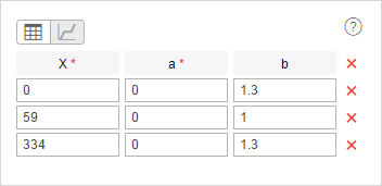
time is the parameter that is present in any message from any device, and the system will calculate the number of the day automatically on its basis. In that way, as the season starts, 30% will automatically be added to the fuel consumption.
Speed source
This section is shown for certain device types for which changing the speed source is supported in the monitoring system.
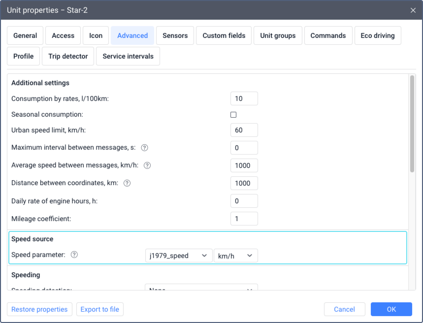
In most cases, the monitoring system uses the values calculated by the device via GPS as speed values. They are stored in the unit messages in the speed parameter. If they are not correct, you can specify the parameter the values of which should be used for the speed parameter.
To set the speed source correctly, follow the steps below.
- In the Speed parameter field, select or specify the name of the parameter (no more than 50 characters) the values of which should be used as speed values. The list shows all the parameters sent by the device, except for the virtual ones.
- Select the unit of measurement in which the device sends speed values (not the unit of measurement which should be shown in the monitoring system). If the unit of measurement is not selected, the system uses km/h.
- Save the changes.
After that, the speed value is taken from the specified parameter.
After that, the speed parameter values from the unit messages begin to be replaced by the values of the specified parameter in all parts of the system without the possibility of recovery. If the messages don’t contain the specified parameters, the usual values of the speed parameter are used.
The speed value of the specified parameter is not taken into account in the system if the location is determined by LBS (see the Allow positioning by cellular base stations option). Namely, the unit tooltip, the extended unit information and the Speed column in messages show 0.
Speeding
In this section, you can select the method which should be used to determine speed limit violations on which you can later run a special report. Also, if you are running a report with a track, you can enable an option to add speeding markers to the map.
The following items are available for selection: None, Fixed limit and Road limits.
None (default)
The system doesn’t register speed limit violations. This item is selected by default.
Fixed limit
Speed limit violations are registered in accordance with the specified conditions.
In the Fixed speed limit field, specify the maximum allowed speed for this unit. If the speed is higher than the specified value, the system registers a violation.
In the Min. speeding time field, specify how long the violation should last. If the violation lasts less than the specified time, the system doesn’t register it.
Road limits
This option registers violations dynamically based on the official speed limits for passenger cars provided by Gurtam Maps. This feature is active for roads with a speed limit higher than 30 km/h.
If a layer with speed limits has been added to Gurtam Maps at the user’s request, they are given priority in this user’s monitoring system.
To configure this, set the following fields:
- Tolerance on speeding: Specify by what value the unit can exceed the speed limit so that the system doesn’t register a violation. For example, the map shows a road limit of 60 km/h. The field value is 10 km/h. This means that if the unit is moving at a speed of up to 70 km/h, no violation is registered.
- Min. speeding time: Specify how long the violation should last in order for the system to register it.
If you specify 0 in the Min. speeding time field, a speed limit violation is registered even if the unit sends one message with a speed value higher than the selected limit. The duration of this interval is indicated in reports as 00:00.
Adding custom speed limits
To add your own custom speed limits to the map, follow these steps:
- Contact customer service to determine which source (HERE Maps or OpenStreetMap) provides the speed limit data for your region.
- Follow the appropriate guide based on the source for your region:
Driver activity by online data
This functionality is considered outdated and not recommended for use.
In this section, you can select the source of information about the activity of the driver. This data helps to monitor in real time whether the driver sticks to the work and rest regime.
The information about the driver activity is shown in the tooltips of the unit and of the driver and in the extended information about the unit if the Driver activity by online data option is enabled in the user settings. Also, you can see this information in the Driver activity and Infringements tables in reports on drivers and in the Tacho View application.
The following data sources are available for selection:
| Source | Description |
|---|---|
| None | New data on the driver activity is not calculated. But the tooltip of the unit or driver and the extended unit information display the data on driver activity calculated earlier, if any. |
| Parameters from tachograph | Online data on the driver activity is transmitted to the device from the tachograph installed on the vehicle, and then it is sent to the system. Not all of the device types support this feature. |
| Assignments and trips | The activity of the driver assigned to this unit is determined by online data as follows:
|
Wialon doesn’t recalculate online data on the driver activity for the past period. Therefore, online data can only give you an approximate idea of whether the driver sticks to the work and rest regime. If you change the trip detector settings or data on the driver assignments, these changes are not applied to online data for the past period and are not reflected in reports.
You can get accurate data on the driver activity only in reports and in the Tacho View app using files from the driver card as a data source.
Questions and answers
Unit caption color
On the map, each unit can be identified by a label that shows its name and the name of the assigned driver. To display these labels, enable the Unit name and Driver’s name options in the map visible layer settings.
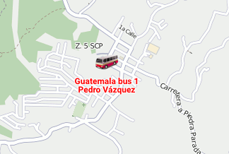
Customizing unit caption color
By default, the names of the units and the drivers assigned to them are shown on the map in red. To change this color for a unit, use the Unit caption color option. You can choose from a predefined palette or use the color picker for a custom shade.

For details on displaying other object names on the map, see Drivers on the map, Trailers on the map, and Passengers on the map.
Track colors
In this section, you can set the color for tracks, that is, the lines of unit movement on the map. The tracks are mapped on the Tracks, Messages, Reports, and Monitoring tabs (the Quick track option).
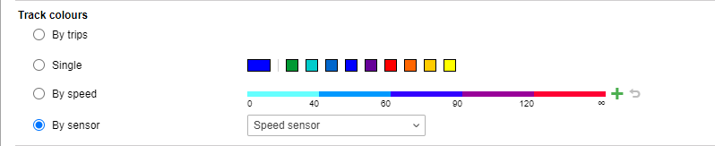
Tracks can be single- or multi-colored depending on the settings according to which the color is determined. You can select one of the four options:
- by trips
- single
- by speed
- by sensor
The option selected in this section is also selected for the Tracks tab by default.
| Item | Description |
|---|---|
| By trips | The track is divided into sections of different colors, each of which corresponds to one trip. Trips are detected by the trip detector. |
| Single | This option applies a single color to the entire track. It is recommended when displaying tracks for a unit group, as it ensures that each unit track is visually distinct and easy to follow. You can select a color from the palette or specify a custom one with the color picker. When you generate multiple tracks in a row, the system automatically applies the next color from the palette to each new track. |
| By speed | The track is multi-colored depending on the unit speed. To add an interval, click on the icon The created intervals are shown on the line scale. To edit an interval, click on it, make changes, and click OK. To reset the settings to the default ones, click on the icon |
| By sensor | The track is multi-colored depending on the values of the selected sensor. The list contains the sensors created for the unit. The value intervals and colors for tracks are specified in the sensor properties.If the interval settings have been deleted from the properties of the selected sensor, the system will automatically switch to another sensor that has the intervals configured. In case there are no other sensors with configured intervals, the system will use the By trips option. |
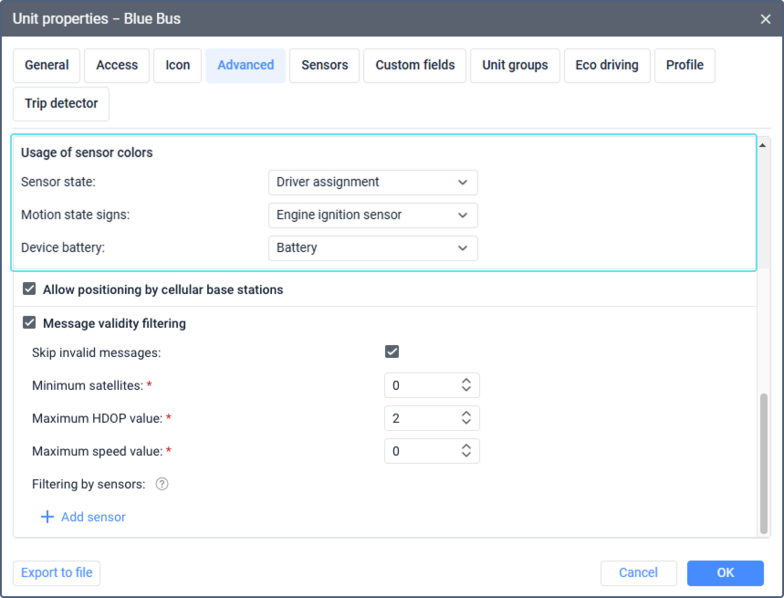
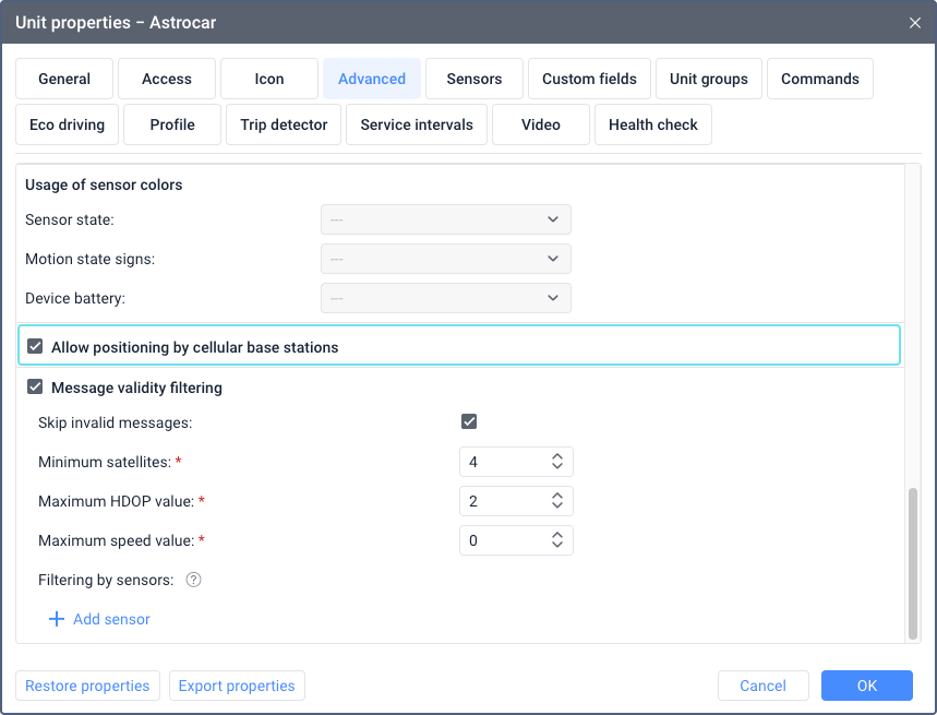
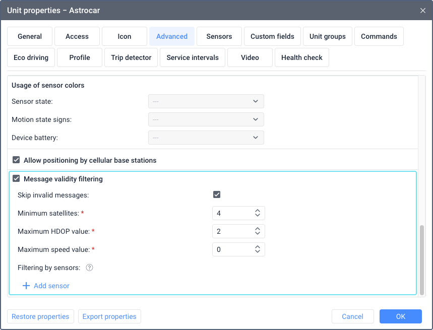
Usage of sensor colors
In this section, you can select the sensors the colors of which should be used for certain interface elements. A sensor is available for selection after you create it and specify its value intervals and the colors corresponding to them.
Below are the interface elements for which the colors of the selected sensors are used.
| Item | Description |
|---|---|
| Sensor state | The colors of the selected sensor are used for the Sensor state option in the work list on the Monitoring tab and in the menu of monitoring options on the map. |
| Motion state signs | The colors of the selected sensor are used for motion state signs on the map. |
| Device battery | The colors of the selected sensor are used for the Device battery option in the work list on the Monitoring tab and in the menu of monitoring options on the map. Also, the sensor selected here is used on the Health check tab for the Device battery level criterion. To configure a sensor which shows the device battery level, you should create a custom sensor with the parameter in which data on the battery is received from the device. If the data is received in volts, and not in per cent, then you should also fill in the calculation table in the sensor properties so that the data is displayed correctly. |
If the unit doesn’t have suitable sensors, these options are inactive.
Allow positioning by cellular base stations
This option works for devices which support positioning by cellular stations. To see a list of such devices, select the required section on the Hardware tab and apply the LBS filter. The option allows using cellular base stations (LBS) to determine the unit location, for example, when GPS data is not valid. The data obtained this way is not as accurate as GPS data and shows only an approximate location.
LBS data is used in the following cases:
- when the Allow positioning by cellular base stations option is enabled and there are no messages with GPS data for more than five minutes;
- when the Allow positioning by cellular base stations option is enabled and the messages with GPS data received over the last five minutes don’t meet the specified filtering criteria.
During these five minutes, the system shows the unit location and motion state determined by the last valid GPS data. The LBS messages received in the meantime don’t affect the displayed unit location and motion state, but you can see these messages in reports and in the table of messages.
After five minutes, if the values of all LBS parameters (mnc, mcc, lac, cell_id) remain the same as in the last message with valid GPS coordinates, these coordinates continue to be regarded as the last known unit location and the motion state icon doesn’t change. As soon as new values of the LBS parameters are received, a new unit location is shown according to them, and the motion state icon changes to  .
.
If the unit location is determined by LBS, the speed values are not taken into account in the system. In this case, the unit tooltip, the extended unit information and the Speed column in messages show 0.
Messages with LBS data are not taken into account in the trip detector and eco driving.
Questions and answers
How do I know that the unit location is determined by LBS?
If the location of the unit is determined by LBS, you can tell this by how it is displayed on the map and by the icon which is shown opposite the unit name in the work area of the Monitoring tab.
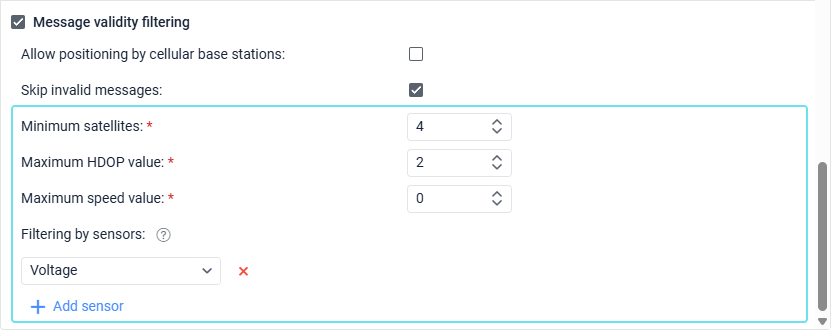
Message validity filtering
All messages from units are registered in the database. However, some messages may be invalid, for example, due to data outliers or lack of coordinates. Such messages distort mileage values, tracks, indicators in reports, and so on.
To solve this problem, Wialon provides message validity filtering. This feature allows you to specify the criteria that determine whether a message is valid or not. If a message is invalid, it is saved in the database without the information received from GPS: that is, without speed, coordinates, number of satellites, altitude, and movement direction. The other data from such a message (for example, sensor values) is saved and can be used in the system.
In addition to the validity criteria, this section provides an option for skipping messages which are invalid according to the unit device. See the description of this option below.
The settings specified here apply only to new messages received after you save the changes.
Regardless of the settings in this section, any message without coordinates or at least one zero coordinate (longitude or latitude) is considered invalid.
Skip invalid messages
The option allows ignoring the GPS data identified by the device as invalid. Some devices (controllers) send special parameters which identify invalid coordinates. Also, the current time and the last valid coordinates are specified in the message. The system considers such a message to be without positional data and doesn’t use it for mapping tracks, determining the location, and so on.
Message validity criteria
The validity criteria follow the OR logic: a message is considered invalid if it fails to meet at least one of the following criteria.
| Criterion | Description |
|---|---|
| Minimum satellites | In this field, you can specify the minimum number of satellites that should be used to determine the coordinates in order for the message to be considered valid. The recommended number is at least four. The value can’t exceed 255. |
| Maximum HDOP value | In this field, you can specify the maximum HDOP value with which messages are considered valid. HDOP stands for horizontal dilution of precision. The smaller this value is, the more accurate the coordinates are. The value can’t exceed 9,999. |
| Maximum speed value | In this field, you can specify the limit for speed values. If it is exceeded, the message is considered invalid. You can’t indicate a value greater than 9,999. If 0 is specified, this filtering criterion is not taken into account. |
| Filtering by sensors | Here you can add sensors which should be used to filter messages. If the value of the selected sensor is 0, the message is considered invalid. To add a sensor, click Add sensor and select the necessary one from the list. You can add several sensors. |
Determine the location by Wi-Fi points
This option is displayed for devices that can determine the location by Wi-Fi points. To see a list of such devices, select the required section on the Hardware tab and apply the Wi-Fi positioning filter.
When the Determine the location by Wi-Fi points option is activated, the options described below become available.
| Option | Description |
|---|---|
| Minimum number of Wi-Fi points | Here you should specify the minimum number of Wi-Fi points with which the messages should be considered valid. You can indicate only an integer value. The minimum allowed value is 2, the maximum one is 255. |
| Maximum number of Wi-Fi points | In this field, you should specify the maximum number of Wi-Fi points which should be taken into account when determining the unit location. If the number of available points is greater than the number indicated here, the points with a stronger signal are used. You can indicate only an integer value. The minimum allowed value is 2, the maximum one is 255. |
| Location accuracy, m | In this field, you should specify the location accuracy in meters. The smaller the value, the more accurate the received coordinates. A message is considered invalid if its accuracy value is greater than the specified one. You can enter an integer or fractional number greater than or equal to zero. The maximum allowed value is 10,000. |
Messages with Wi-Fi data are not taken into account in the trip detector and eco driving.
If the Allow positioning by cellular base stations option is also enabled for the unit and there is valid GPS, LBS and Wi-Fi data, the system determines the unit location using Wi-Fi data in the first place. If Wi-Fi data is invalid (that is, doesn’t match the specified settings or the point address hasn’t been found), the system uses GPS data. LBS data is the last to be used.
You can see that the unit location has been determined by Wi-Fi points in the following places of the system:
- in the Motion state section of the Dashboard tab;
- in the work list of the Monitoring tab (the Motion state option);
- in the table of data messages from the unit (the messages with the unit location determined by Wi-Fi are highlighted in purple).